This procedure guides you through the settings
to edit a scenario using the node on the software's user interface (UI). To learn more about individual cell settings, refer to the UI descriptions.
To view a list of the completed edits through the UI, see the log at
the bottom of the view in the Scenario
Graphics node.
-
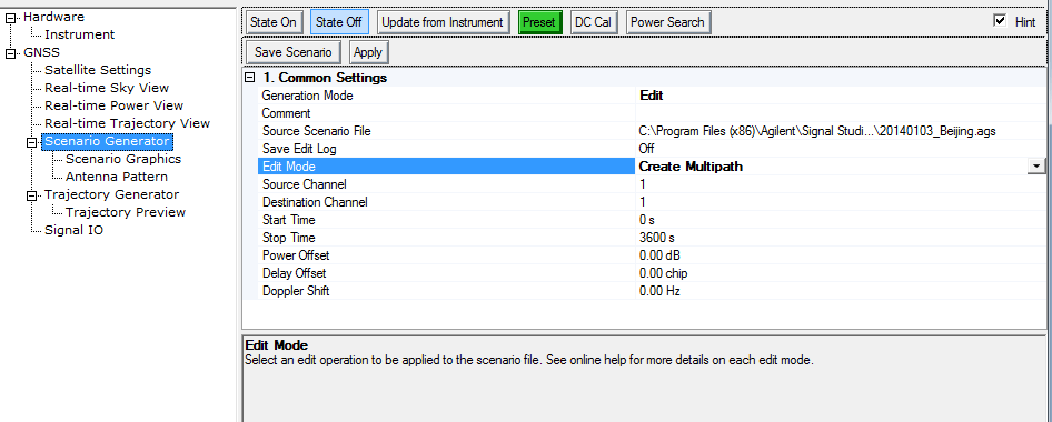
In the tree node, click .
Notice that the software starts with
as the default Generation Mode.
-
Click
and from the
drop down menu, select .
-
View the Comment cell and if desired, enter a new comment or modify an existing comment.
If a comment was entered into the Comment cell during the scenario creation, that same text appears in the Edit mode.
-
Click
the cell,
and use the dialog box button  to launch the
dialog box for navigating to and selecting the scenario file to edit.
to launch the
dialog box for navigating to and selecting the scenario file to edit.
-
If
there is a desire to keep track of the edits, click the cell,
and from the drop down menu, select .
The software saves the log file with the same name
(uses .log extension) and at the same location as the edited scenario
file when you click the Save Scenario button.
-
Click
and from the drop down
menu, select the mode:
-
Finish configuring the settings
for the selected Edit Mode:
-
To  Delete Channel
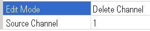
To view active and deleted
channels, click the Scenario Graphics node.
-
Click ,
and enter the channel to delete.
-
Click the
button.
-
Repeat Steps a and b to delete another channel.
-
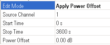
To Apply Power Offset
-
Click
and set the channel to which the offset applies.
If an offset was set in
the original file, this offset is added to the original offset.
-
Click the
cell and enter the time location within the scenario where the power offset
begins.
-
Click the
cell and enter the time location within the scenario where the power offset
stops.
-
Click ,
and enter the amount of the offset that occurs from the Start time value
to the Stop time value.
-
Click the
button.
-
Repeat Steps a–e
for applying additional power offsets.
-
To Equalize Power

All of the satellite power settings in the
scenario are relative to each other, so when you equalize the power, it
sets all of the satellites to 0 dB. The actual output power is determined
by the signal generator's amplitude setting.
-
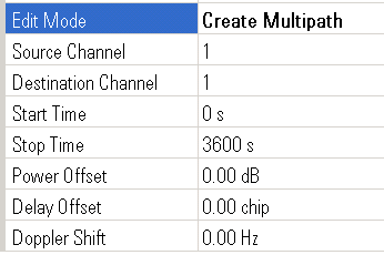
To Create Multipath
-
Click
and enter the index of the satellite channel that is to receive the create
multipath operation.
-
Click
and enter the index of the channel that will store the newly created multipath
channel data.
-
Click the
cell and enter the time location within the scenario where the create
multipath operation begins.
-
Click the
cell and enter the time location within the scenario where the create
multipath operation ends.
-
Click ,
and enter the power scale to be applied to a specific satellite channel.
-
Click ,
and enter the time delay of the multipath channel in GPS chips.
-
Click ,
and enter the Doppler shift of the multipath channel in Hz.
-
Click the
button.
-
Repeat Steps b–h
for applying additional multipaths to the same source channel, or Step a–h for applying multipaths to another Source Channel.
-
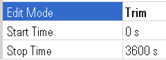
To Trim
-
Click the
cell and enter the start time location within the scenario that marks
the new start time location.
For all channels, the software deletes the
portion of the scenario with a time that is earlier than the value entered.
-
Click the
cell and enter the stop time location within the scenario that marks the
new stop time location.
For all channels, the software deletes the
portion of the scenario with a time that is later than the value entered.
-
Click the
button.
- To make further edits using
another mode, repeat Steps 6 and 7.
-
When all changes have been
made, click the
button to launch the dialog
box for selecting a location and saving the file.